Preliminary remark
The magnetic switch allows you to start and stop the sensor from the outside. We use a reed contact (normally closed contact) for this purpose, which we attach to the housing wall from the inside. If a magnet is now held in the right place from the outside, the circuit is interrupted. So if you take the magnet with you after installation, the sensor starts to measure. When you come back to dismantle the sensor, push the magnet back on and stop the measurement.
You are completely free to decide where you install the reed contact in your circuit and where it is positioned on the housing. The main thing is that the power supply to the Teensy can be interrupted by the contact.
The 3D printed parts linked below are aligned to the reed contact also linked and kept as small as possible. If you want to make changes to the parts, you can use this FreeCad project file.
What you need
Tool
 Soldering iron + solder
 Soldering pliers
- Shrink tubing (5cm, optional)
- Second glue
Parts
- finished sensor
- Reed contact (normally closed contact)](https://www.amazon.de/dp/B088CQL44X)
- Contact holder inside (3D printed part)
- Magnet holder (3D printed part)
- Magnet holder](/parts/MagnetSlider_mOO-Citrad.stl) (3D print part)
- Some extra cable (optional)
This is how it works
Preparation
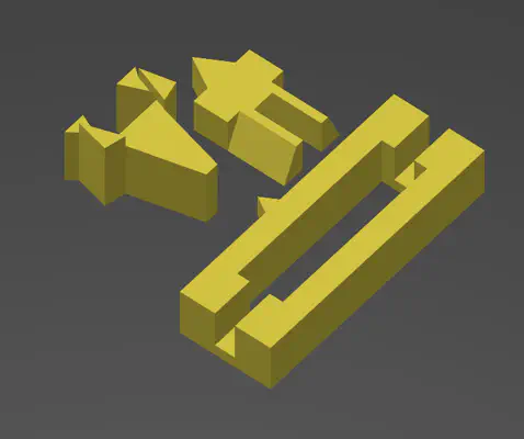
All required 3D printed parts
You need to produce these three parts using a 3D printer. They are designed so that both the reed contact and the magnet rest directly on the housing wall. If you want to use your own designs, you must also take this into account so that the reed contact is triggered.
Gluing on the holder
All required 3D printed parts
All required 3D print parts
-
first glue the reed contact holder into the housing. Make sure that the small triangle points towards the housing and that the tip of the triangle is not positioned higher than the indentation on the edge of the housing where the cover will later click into place.
-
Now glue the magnet holder on the outside so that the triangle is aligned and positioned at the same height (eye measurement is sufficient) as the triangle on the reed contact holder on the inside. It is also important that the narrow part of the bevel points towards the housing. Otherwise it will be impossible to slide the magnet on later.
Wiring of the reed contact
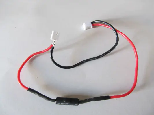
Pluggable integration variant makes the use of the magnetic switch optional.
You can freely choose where to install the reed contact in the circuit. You can solder it permanently or make it pluggable with an extra plug and socket as an optional part, as shown here.
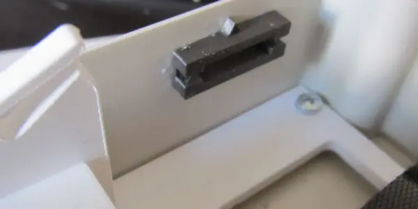
As soon as the wiring is complete, the reed contact must be inserted into the holder with the square protrusion pointing towards the inside of the housing. Make sure that it really is fully seated against the housing wall.
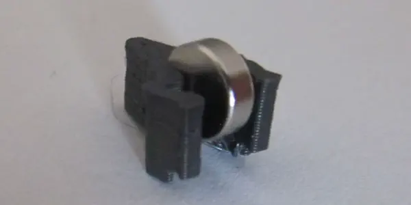
Test the correct orientation of the magnet
Magnet test plugged in to test orientation
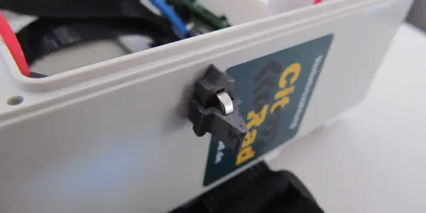
Magnet glued into the magnet holder.
The reed contact will only reliably interrupt the circuit if the magnet is applied in the correct orientation. It therefore depends on which side of the magnet points to the left and which to the right. To find out the correct orientation, insert the magnet without its holder (3rd 3D printed part) into the holder and connect the rest of the circuit. If the sensor remains off (no LEDs light up/flash), you have already found the correct orientation. Otherwise, turn the magnet around and repeat the test. Alternatively, you can of course also measure for continuity with a multimeter.
Now that you know the correct orientation, you can glue the magnet into the holder. The holder is designed so that it can only be slid open in one direction (small locking lugs at one end). Glue the magnet into the holder so that it is correctly oriented when you slide it on. Make sure you press the magnet fully into the holder so that the distances are correct afterwards.
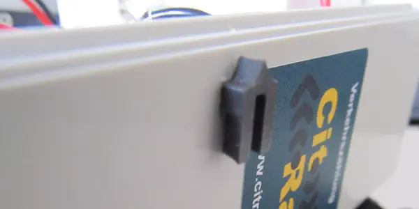
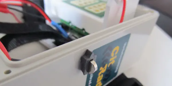
The final “off” position
This is what the off-position looks like
When everything is glued and plugged together, you can connect the circuit completely. As long as the magnet is in place, no current will flow. Only when you remove the magnet holder/magnet does the measurement begin.