How to connect the individual electronic parts to form a functioning sensor
Now it’s getting electronic. You should be able to solder for the following work. We will now explain the rest in as much detail as possible.
Soldering all the components together can be challenging. If you don’t have much experience in soldering, look for help with the soldering work
2.1 - Teensy developer board
All preparation steps for the Teensy developer board
What you need
Tool
Cutter knife
Soldering iron + solder
Micro USB cable + 5V power supply/USB port of the laptop
Parts
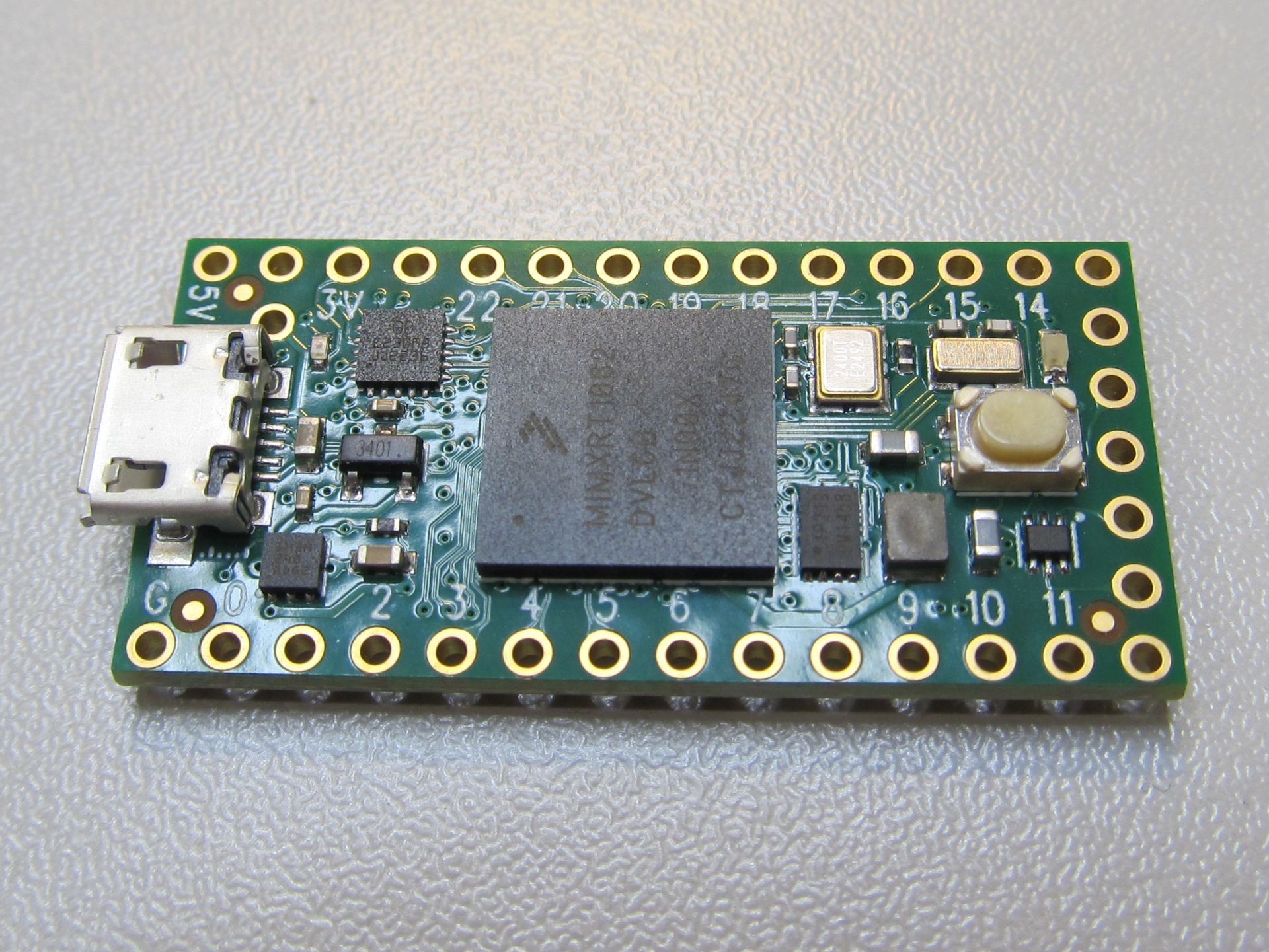
Teensy developer board
Button cell holder
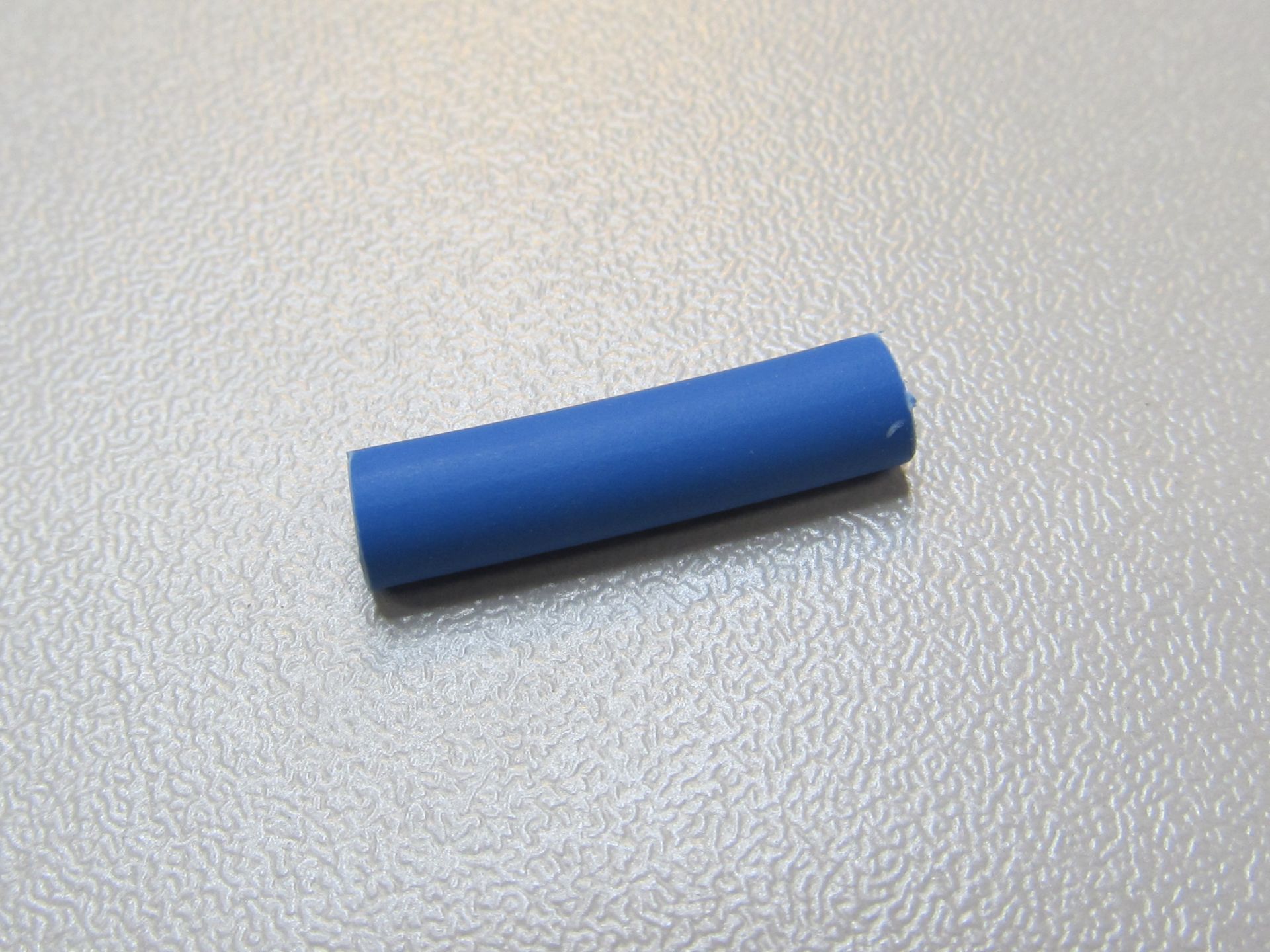
Shrink tubing (1cm)
This is how it works
Function test
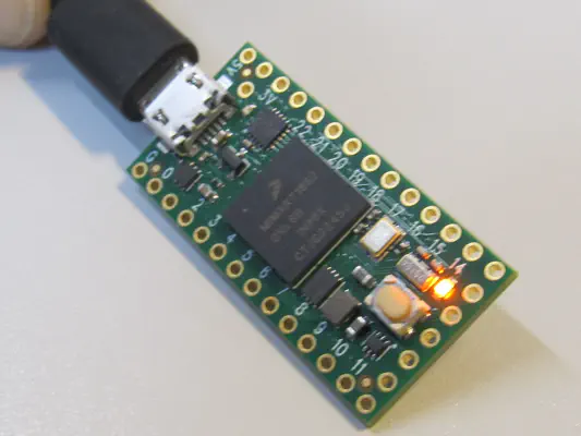
The red LED should flash when powered via USB.
The Teensy should basically work before you start with the customizations. Connect the Teensy developer board to a power source via USB. The red indicator light should flash. Now disconnect the USB cable again.
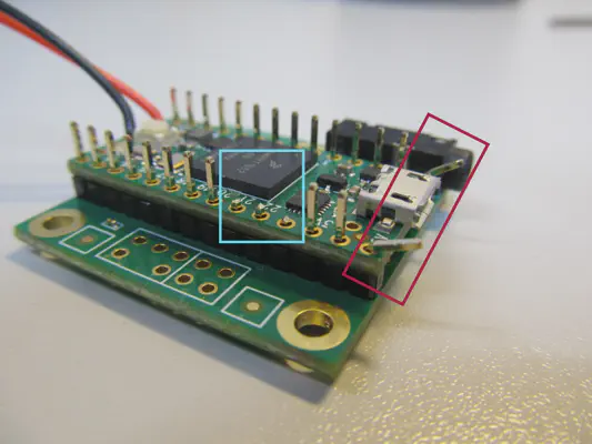
Disconnect contact for USB power supply
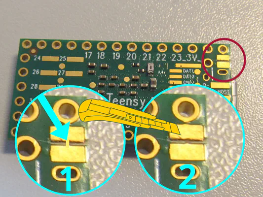
The connection between the two rectangular contacts (circled in red) must be removed. Circle 1 and 2 show how.
The Teensy developer board is to be powered by a battery pack for this project. To ensure that it is not inadvertently supplied with power via battery pack and USB, we must first deactivate the power supply via USB.
In the photo, two square contacts are circled in red. The two traces are connected by a small trace (see arrow in circle 1). You have to scrape this away with the cutter knife until it looks something like in circle 2.
To check, connect the Teensy to a power source via USB again. The red LED from the first step should no longer flash/light up.
You can only continue if the Teensy’s red indicator light no longer flashes/lights up. Otherwise you will have to rework.
Prepare the button cell holder
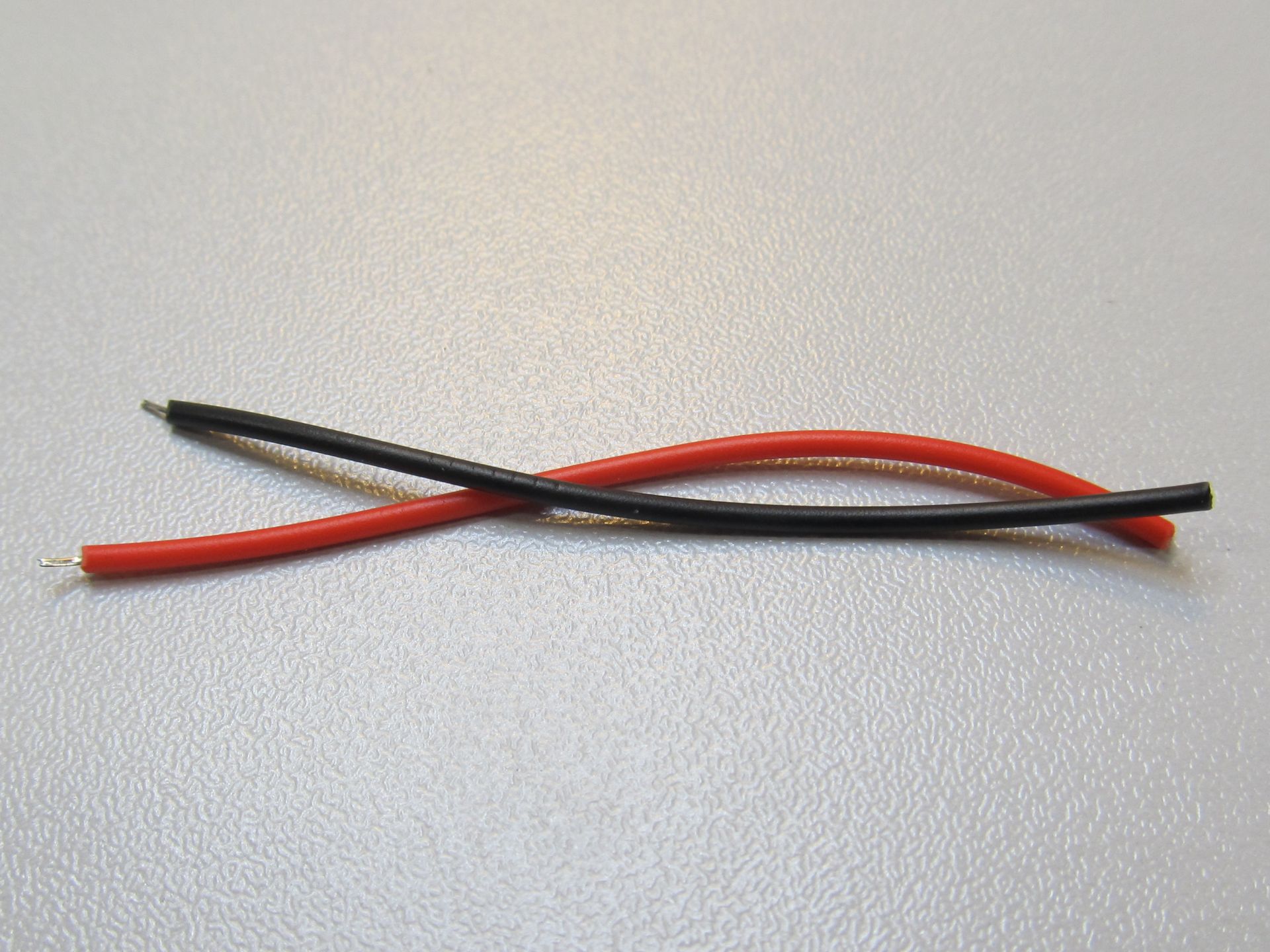
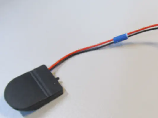
Button cell holder with shrink tubing over the connection cables
A button cell also supplies the Teensy with power when it is not connected to the battery. This means it does not lose its time and date settings while you are charging the battery.
Before you can solder the button cell holder to the Teensy, a small piece of shrink tubing (1 cm) must be pulled over both cables (but not yet heated). This will provide strain relief later.
Please only insert the button cell when you are asked to do so in the instructions. Otherwise there is a risk of short circuits during soldering.
Solder on the button cell holder
Soldered button cell holder
The red cable must be soldered to pin 32, the black cable to pin 28. The pin designations can be found on the back of the Teensy
It is important that the cables on the underside of the board do not protrude. The SD card slot from the audio board will be located here later. This must not come into contact with the solder joints.
Preparation of the Audioshield for assembly with the developer board
What you need
Tool
Side cutter
Pointed pliers
Soldering iron + solder
Soldering pliers
Parts
Teensy developer board
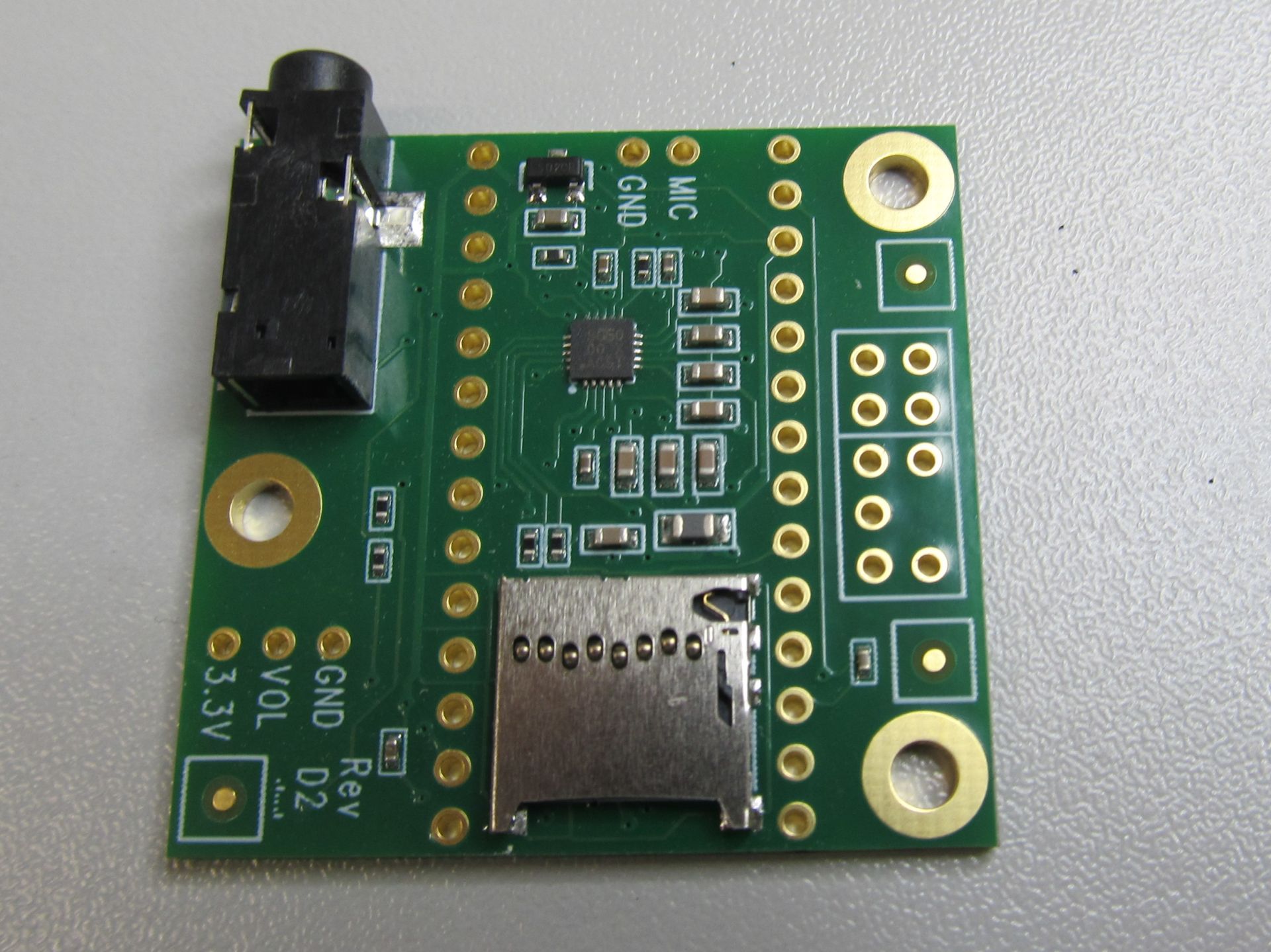
Audio shield
2-core cable (4cm)
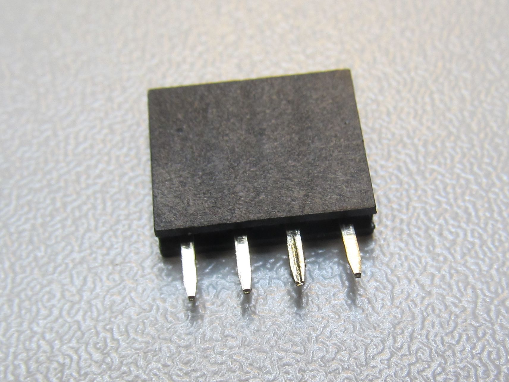
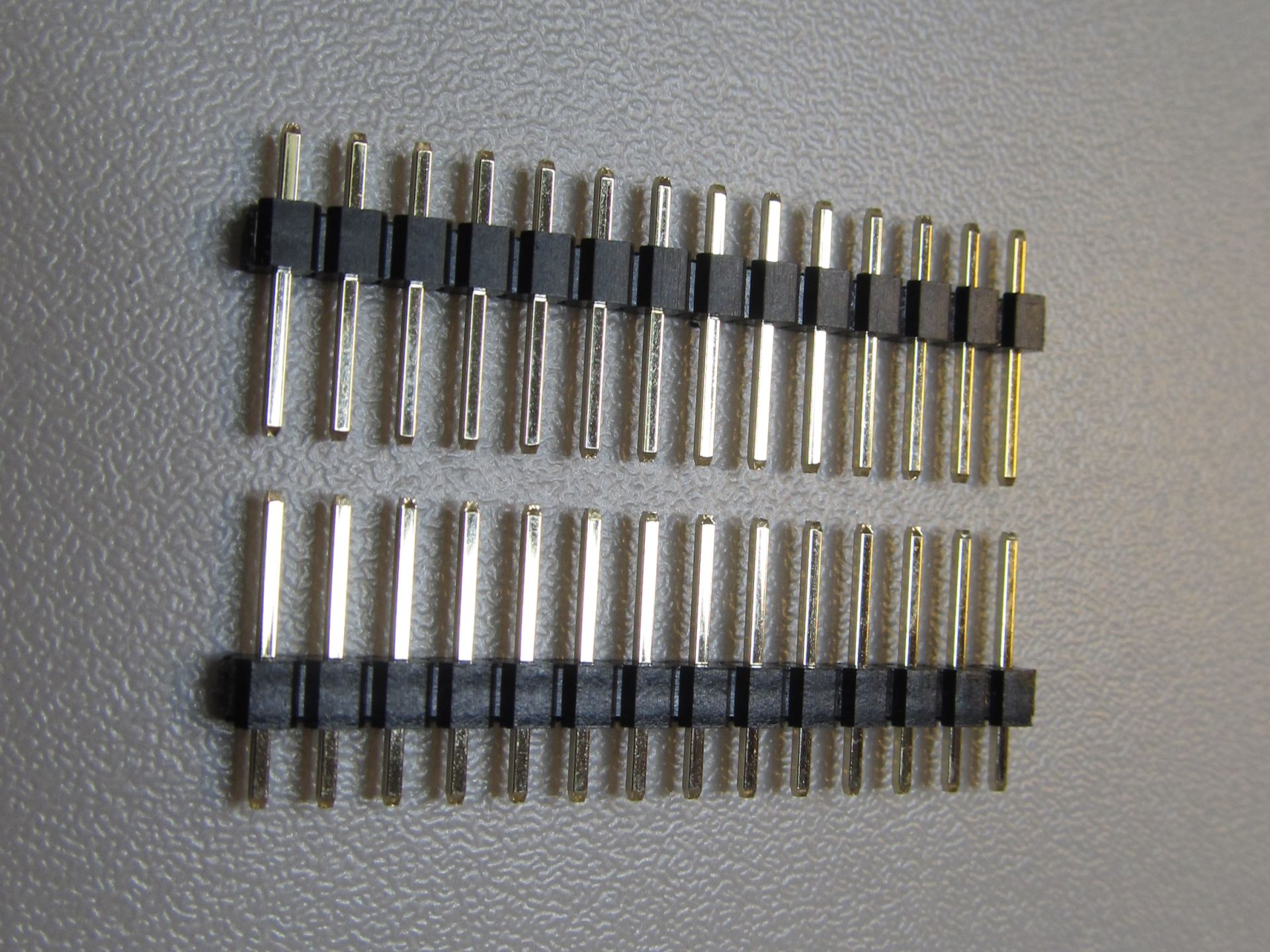
40-pin header
Battery socket
Battery pack (only for checking the correct polarity when soldering)
How it works
Shorten the pin header
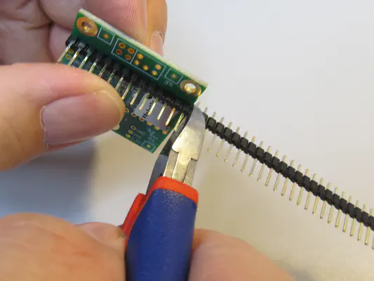
Shorten the pin header to the length of the audio shield
The 40-pin strip is too long for the audio shield. Simply insert it flush on one side onto the row of holes in the audio shield and cut off the excess with the side cutter.
Do the same for the opposite side. You should now have two strips of the same length (14 pins) and a shorter remaining piece.
The remaining piece is no longer needed. It is best to put it aside so that you don’t use it by mistake.
Solder the pin headers
The short ends of the shortened pin headers are soldered to the audio shield.
Now insert your two pin headers of the same length into the audio shield with the short side from above (side with jack connection and Micor SD card slot) and solder the headers to the back of the audio shield pin by pin.
Set up Teensy and customize pins
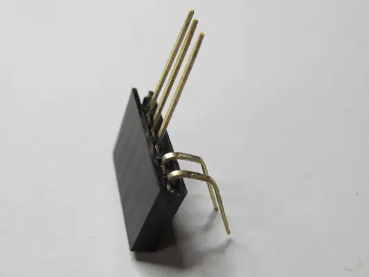
Clip off the pins (cyan) or bend them (red).
Now place the Teensy on the long pins. The USB socket points upwards and in the same direction as the audio shield's jack connection.
Use needle-nose pliers () to bend the pins on 5V and GND diagonally forwards as shown in the photo.
In order to be able to solder the voltage transformer properly later on, use the side cutter () to cut off pins 21, 22, 23.
Now solder all the pins to connect the two boards.
Prepare the socket for the power supply
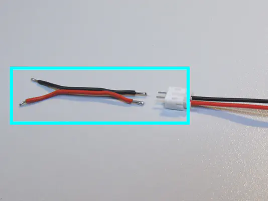
Solder the socket cable together
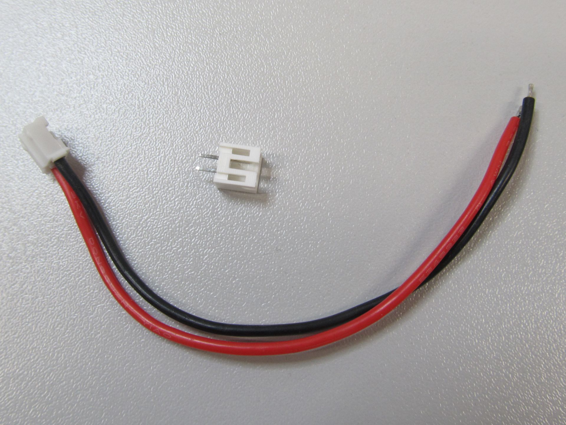
In the picture you can see the two-core cable (4 cm) framed in cyan and the connection socket. The connection socket still contains a plug (with cable) that was included in the scope of delivery. This can be a help when soldering. However, you will no longer need the plug and cable in the following steps.
Cut the two-core cable (4 cm) a little on both sides and strip all ends. (Already done in the photo)
Now solder the cable to the socket so that the polarity matches the plug of the battery pack.
Caution: Some socket/plug sets have the polarity reversed. Always compare whether the plug has the same polarity as the battery pack and only then solder the socket to the cable accordingly.
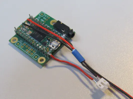
Solder the socket with strain relief
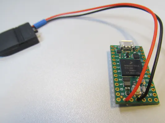
Solder the socket cable together
Now route the cable of the button cell holder (already soldered to the Teensy) over the Teensy in the direction of the USB socket. Then feed the black cable of the battery pack socket from the previous step (coming from the button cell) through the shrink tubing.
Solder the black cable to the bent GND pin and the red cable to the likewise bent 5V pin.
In order to relieve the soldering points for the cables of the button cell holder against tension, all cables are "fixed" in the shrink tubing by heating them. To do this, push the cables of the button cell holder back slightly in the direction of their soldering points so that there is no longer any tension on these cables. Now carefully heat the shrink tubing with a heat gun or lighter.
You must install a voltage converter for the power supply of the radar module. You also need to prepare connections for data exchange between the components.
What you need
Tool
Spitzzange
Soldering iron + solder
Parts
Teensy developer board + audio shield from previous step
Voltage converter
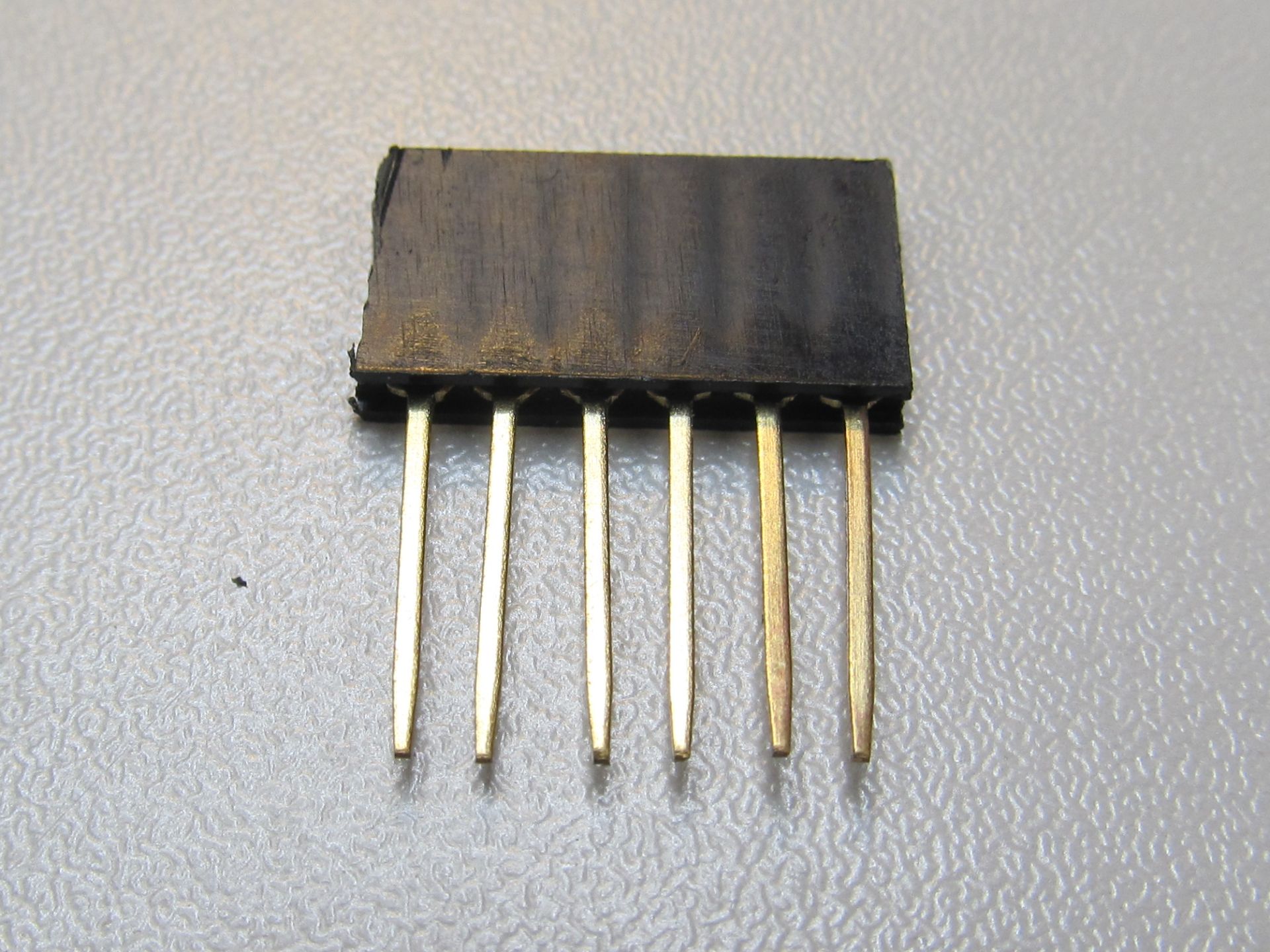
Header 6-pin
Header 4-pin
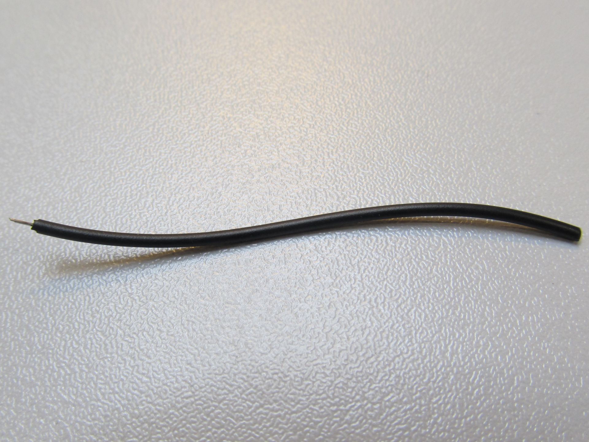
Cable (approx. 4 cm)
How it works
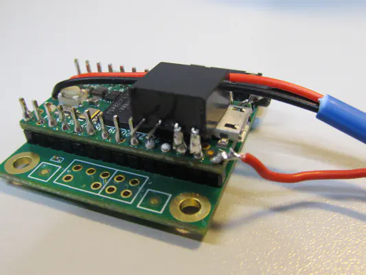
Connect voltage transformer and Teensy
Voltage transformer, soldered to GND and 3.3V of the Teensy
Not in the photo: Place the voltage transformer in front of you with the label facing up and the feet pointing towards you. Now bend the two left feet upwards by 90° as close to the voltage transformer as possible.
See photo: Now place the voltage transformer on the Teensy with the label facing downwards. Make sure that the bent feet are on the left of the two single pins that protrude from the 3.3V contact and GND contact (to the right).
Now you can solder both contact points.
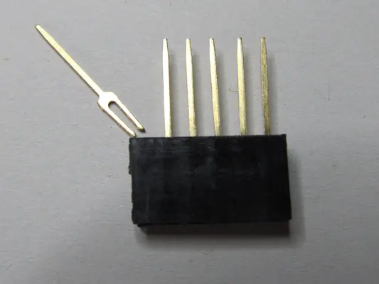
Preparing the plug connection (part 1: header 6-pin)
Pin 1 pulled out
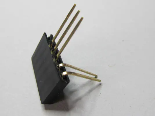
Pin 5 and 6: First bend 90° backwards
Second bend down
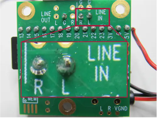
Both pins soldered to the line-in of the audio shield
Click through the bending tabs (1.-4.) to see detailed photos of the individual steps.
Pull pin 1 (far left) out of the connector. It is no longer needed.
First bend pins 5 and 6 (far right) backwards by 90°. Then bend them downwards by approx. 75 degrees with a gap of approx. 4 mm. Both pins must reach the line-in contacts of the audio shield and be soldered there.
Soldered header 6-pin
The header 6-pin must fit on the end of the radar module. It can help if you attach the radar module to the audio shield to bend the pins. The necessary steps are explained from here in the "Assembly" chapter.
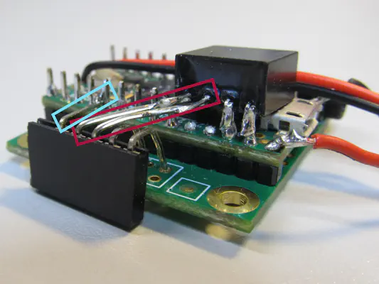
Bend enable (pin 2) to pin 17 of the Teensy and solder together (just fits).
Connect Gnd (pin 4) and Vcc (pin 3) diagonally to the output of the voltage converter (see photo). You may have to bridge this with solder or a short wire. The photo at the bottom of the page shows another top view that may be helpful.
Make sure there are no cross connections. If necessary, bend the wires slightly apart.
Preparing the plug connection (part 2: header 4-pin)
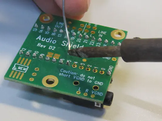
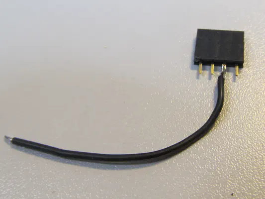
Prepared header 4-pin.
You must solder one end of the cable (4cm) to one of the inner contacts of the header 4-pin.
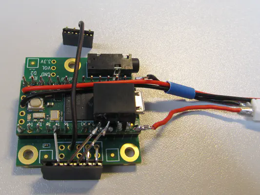
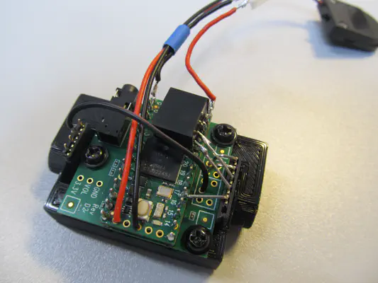
Final result
Final result after executing all steps
Solder the other end of the cable coming from the header 4-pin to GND (lineout or mic) of the audio shield.
In the end, everything should look like the photo.
After you have finished the electronics, the housing must be prepared and everything assembled.
What you need
Tool
Screwdriver
Tap cutter Mx
Cutter knife
Parts
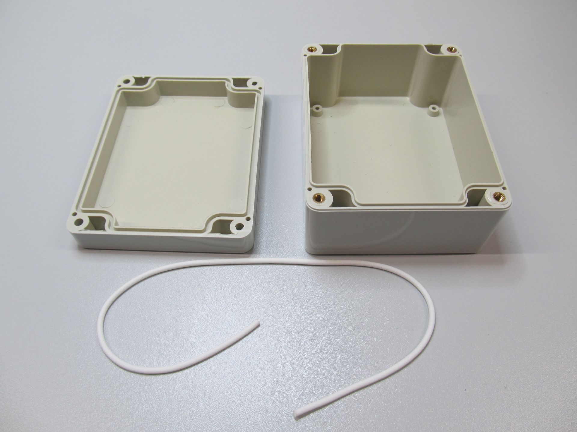
Housing
Battery pack
Lasercut feet
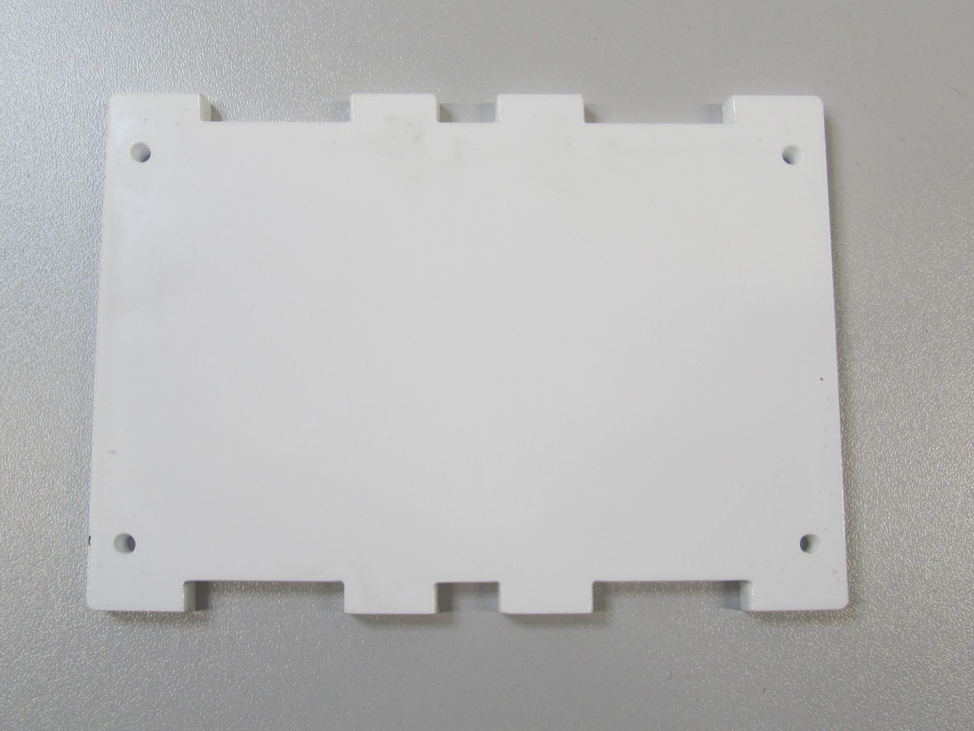
Lasercut adapter plate
Radar bracket
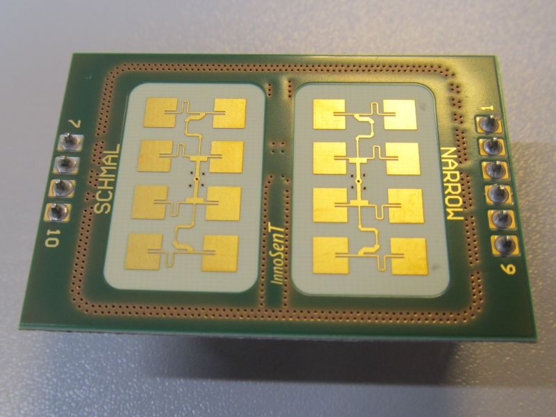
Radar module
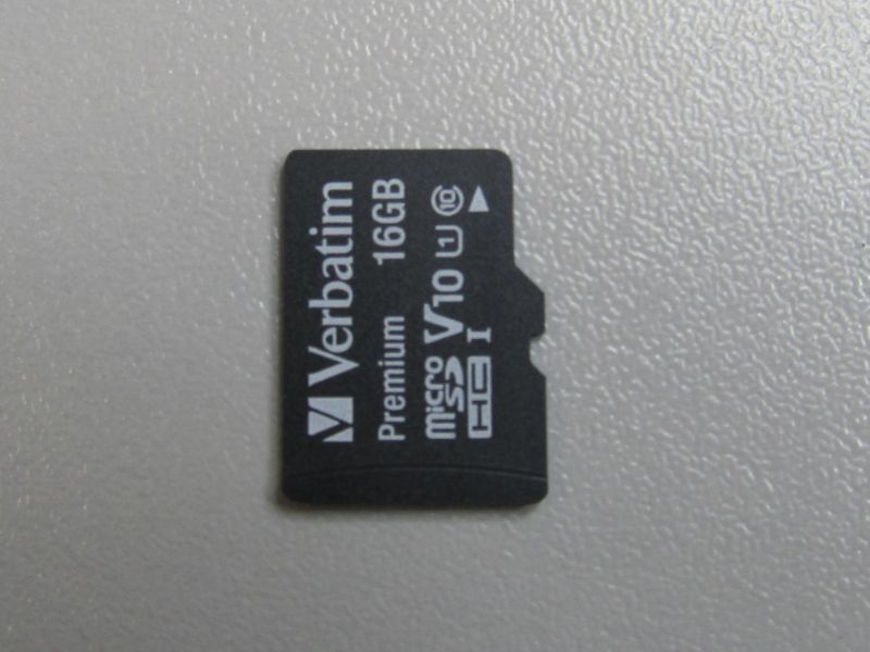
MicroSD card
Everything assembled so far
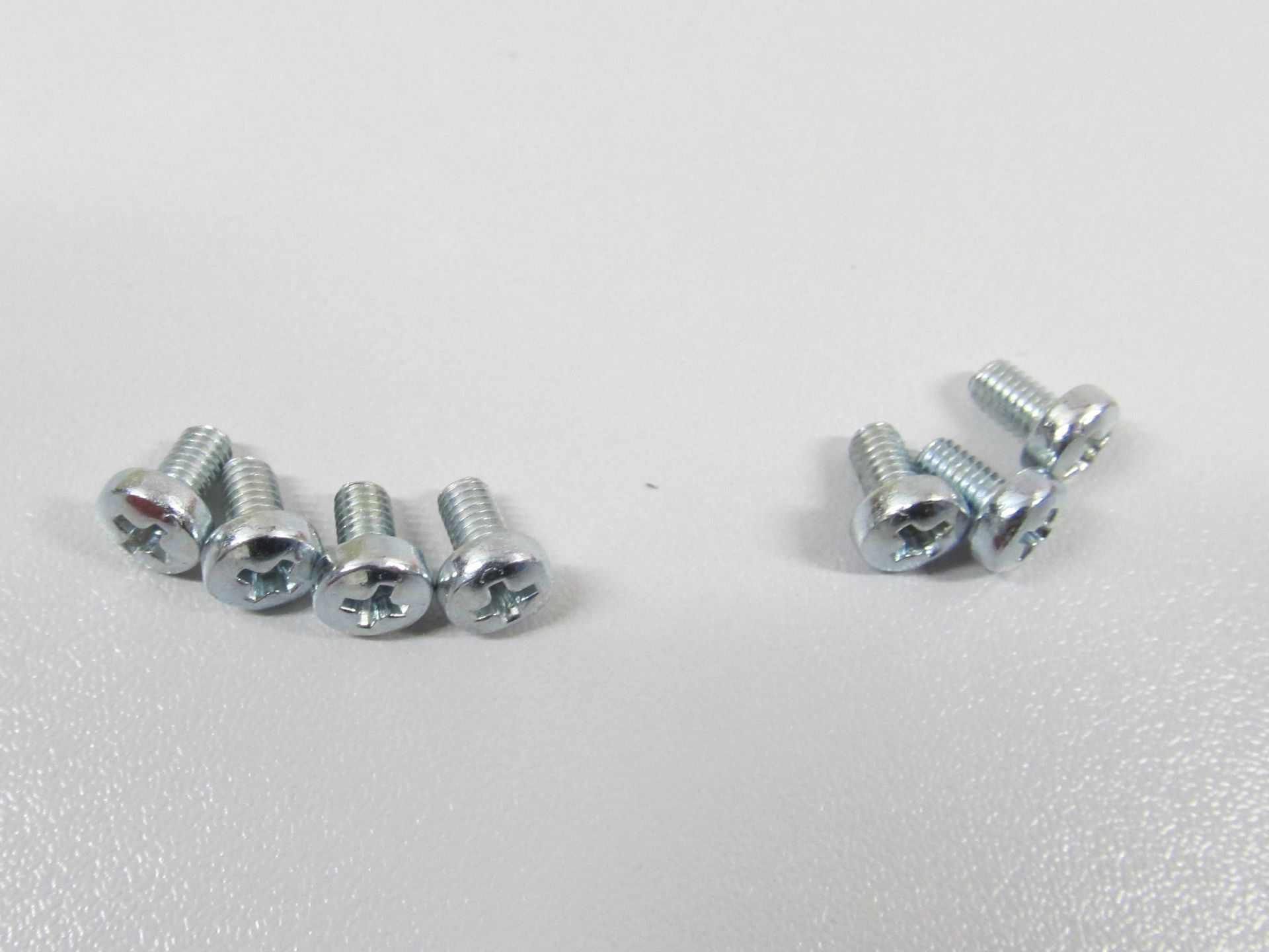
5x M3x5mm screws
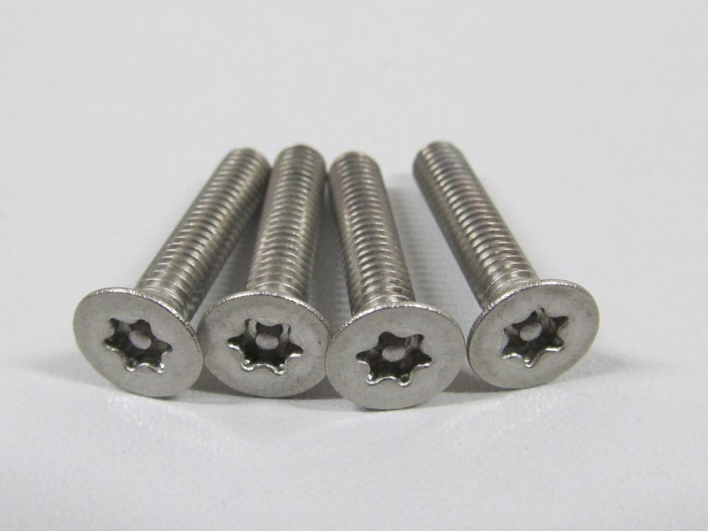
4x M3x14mm cylinder head screws
How it works
Mount the adapter plate
All four holes must be fitted with an M3 internal thread
For mounting on street lamps or the tubes of street signs, we need an intermediate piece between the box and the post.
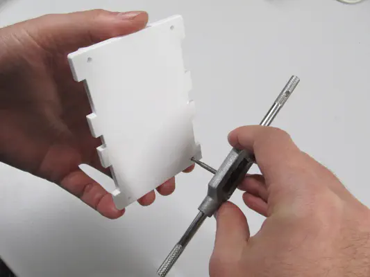
Use the M3 tap to cut an internal thread in each of the four holes in the adapter plate from the laser cutter
Use an Allen key to insert all four cylinder head screws from the inside through the opening and the spacer washer and screw them into the adapter plate.
Now take the 4 M3x14mm cylinder head screws, insert them through the recesses at the corners of the housing (from the inside to the outside) and screw them to the adapter plate.
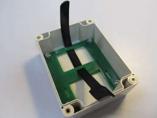
Attach base plate
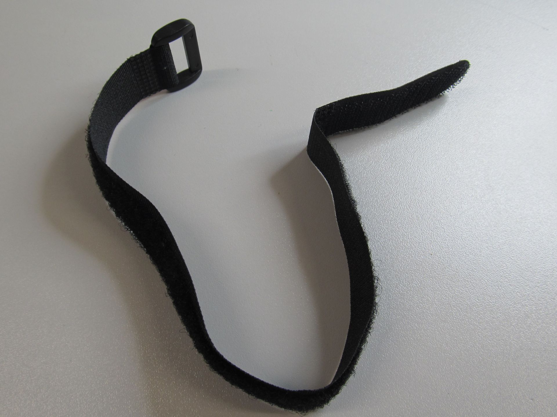
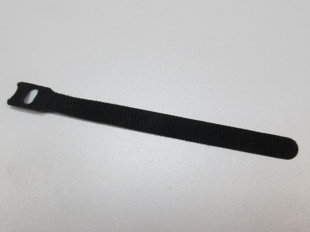
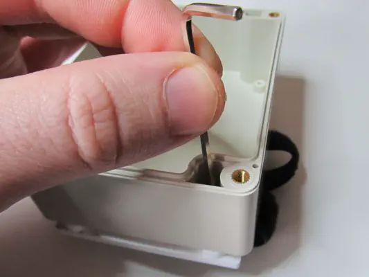
Base plate with Velcro tape for the battery
First insert the Velcro tape into the middle opening with the soft side facing upwards and guide it towards the cut-out
.
Then place the base plate in the housing with the loose Velcro ends facing upwards and screw tight with M3x5mm screws. The orientation of the plate within the housing does not matter.
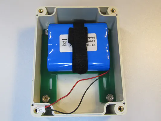
Attach battery
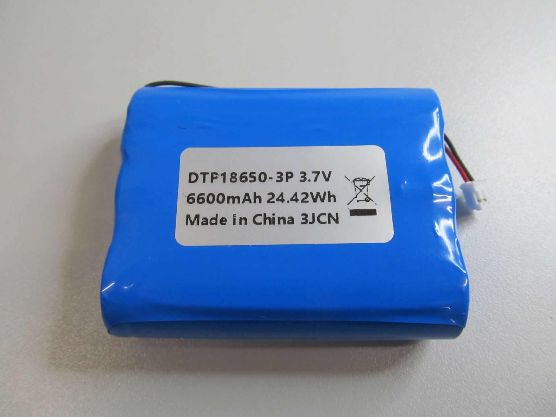
Battery pack in the housing
Attach battery to base plate with Velcro fastener.
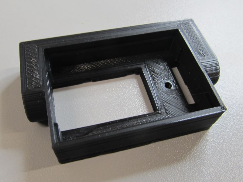
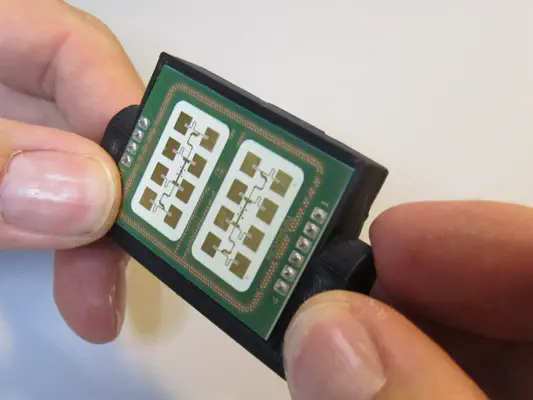
Insert radar module into frame
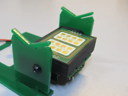
Front
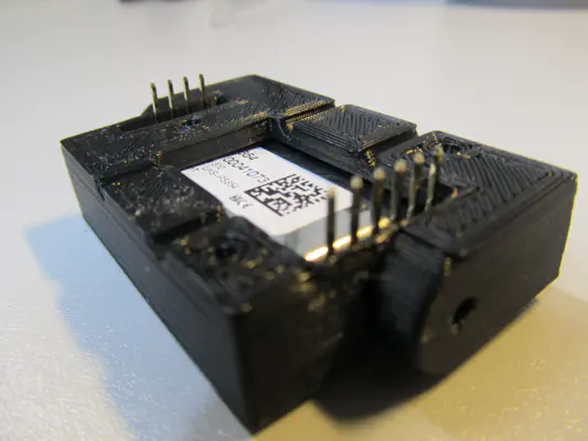
Back
Carefully insert the radar module into the 3D print holder so that the 4 pins protrude through the gap in the holder and the 6 pins on the opposite side protrude through the large opening. The module should be firmly inserted into the 3D printed part at the end.
Attach and screw on Teensy/Audioshield
Front
When attaching the Teensy&Audoshield to the pins of the radar module, you just have to make sure that the holes for the screws in the audio shield match those of the 3D print holder.
Then you can connect the 6-pin connector first and then
Plug in the 4-pin connector so that the cable is soldered to the second pin (as seen from the jack connection).
Then attach the audio shield to the bracket with 3 M3x5mm screws.
Screw the radar module frame to the adapter plates
Screwed-on feet
Now you can screw the feet from the laser cutter to the 3D print holder using one M3x5mm screw each. Do not screw them on too tightly so that you can still move the module.
The longer of the two long edges points towards the wide end of the 3D print holder, while the overhang on the short edge points away from the radar module.
The feet are only in the base plate for the photo. You do not need the base plate here, it can remain screwed into the housing.
Insert micro SD card
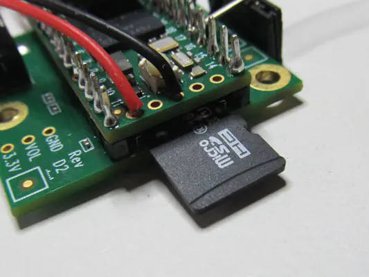
MicroSD card in the slot of the audio shield
The slot for the MicroSD card is now located between the Teensy and the Audioshield. The micro SD card must be carefully pushed into the Audioshield slot with the contacts facing downwards as far as they will go.
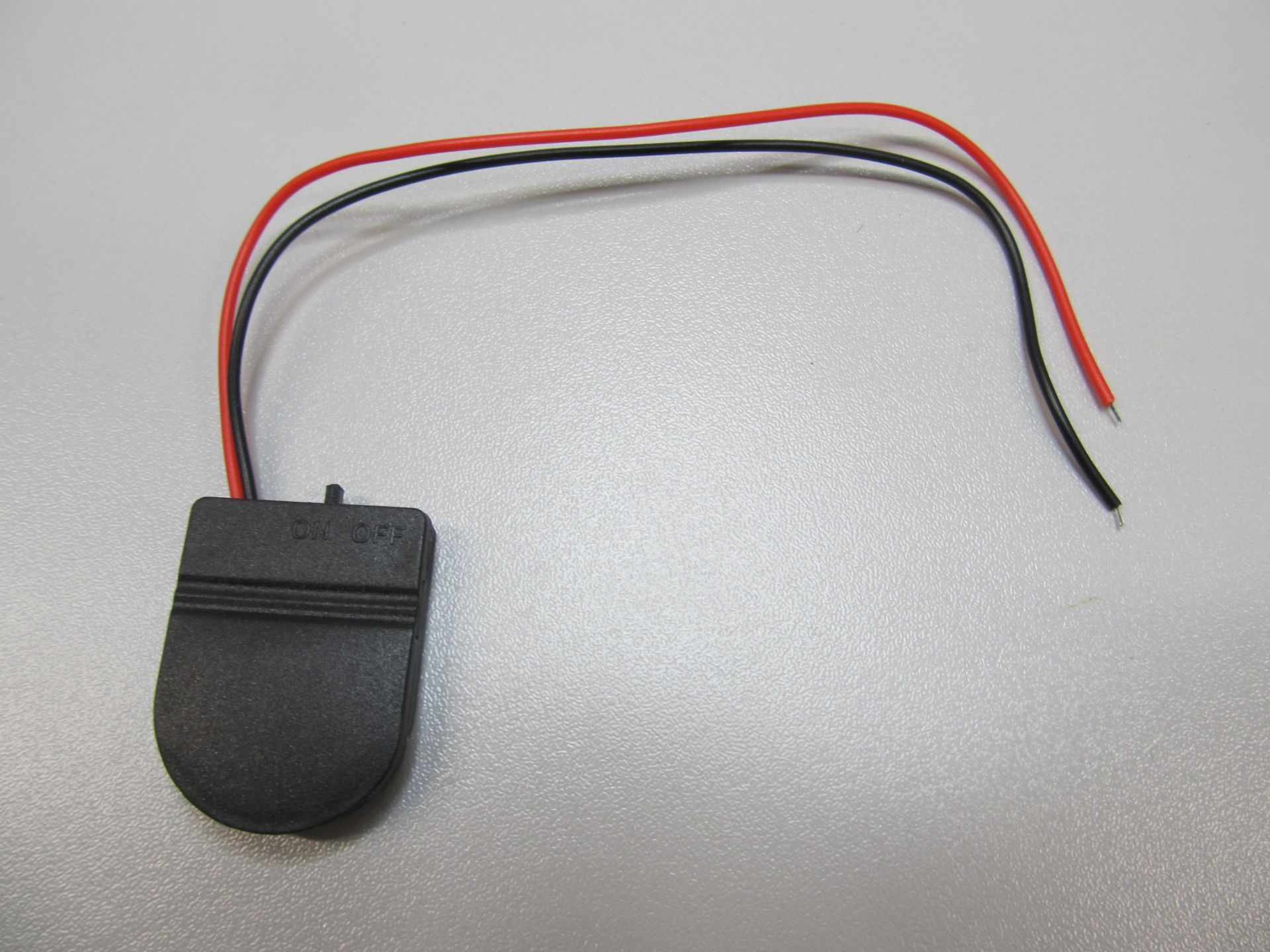
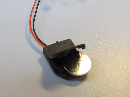
Button cell holder
Button cell holder with button cell
Now insert the button cell into the button cell holder. The positive pole of the button cell must point towards the cover. Make sure that the switch on the housing of the button cell holder is set to "ON" and only switch it to "Off" if you have to change the button cell anyway.
s
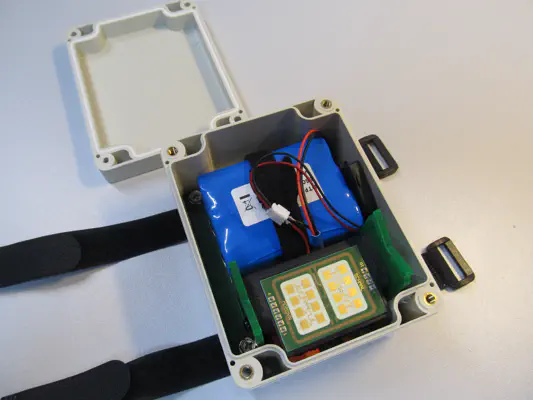
Electronics in the housing
Front
Insert the radar unit next to the battery in the slots provided. The slot for the MicroSD card faces away from the battery. The radar unit is held in place by the screwed-on cover, so you can easily access the MicroSD card at any time.
Space is somewhat limited here. But with a little dexterity, you can insert the radar unit without it getting jammed. If necessary, loosen the battery slightly to allow more play.
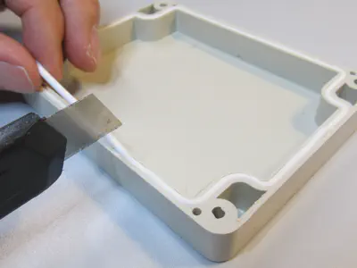
Seal the housing cover
Shortening the rubber seal.
Insert the rubber seal into the groove once all the way around and cut off the excess with a cutter knife.
This step is important to prevent moisture from penetrating the housing.
Congratulations! The hardware part is complete! Before you can screw the cover onto the housing (supplied or M4x20mm security screws), you still need to flash the software onto the Teensy developer board