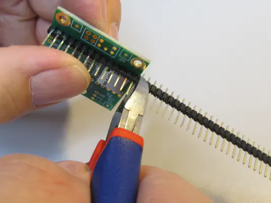
Now it’s getting electronic. You should be able to solder for the following work. We will now explain the rest in as much detail as possible.
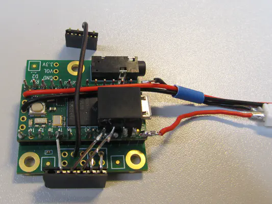
This is the multi-page printable view of this section. Click here to print.
Electronics
1 - Teensy developer board
What you need
Tool
Cutter knife
Soldering iron + solder
- Micro USB cable + 5V power supply/USB port of the laptop
Parts
- Teensy developer board
- Button cell holder
- Shrink tubing (1cm)
This is how it works
Function test

The red LED should flash when powered via USB.
The Teensy should basically work before you start with the customizations. Connect the Teensy developer board to a power source via USB. The red indicator light should flash. Now disconnect the USB cable again.
Disconnect contact for USB power supply

The connection between the two rectangular contacts (circled in red) must be removed. Circle 1 and 2 show how.
The Teensy developer board is to be powered by a battery pack for this project. To ensure that it is not inadvertently supplied with power via battery pack and USB, we must first deactivate the power supply via USB.
In the photo, two square contacts are circled in red. The two traces are connected by a small trace (see arrow in circle 1). You have to scrape this away with the cutter knife until it looks something like in circle 2.
To check, connect the Teensy to a power source via USB again. The red LED from the first step should no longer flash/light up.
Prepare the button cell holder

Button cell holder with shrink tubing over the connection cables
- A button cell also supplies the Teensy with power when it is not connected to the battery. This means it does not lose its time and date settings while you are charging the battery.
- Before you can solder the button cell holder to the Teensy, a small piece of shrink tubing (1 cm) must be pulled over both cables (but not yet heated). This will provide strain relief later.
Please only insert the button cell when you are asked to do so in the instructions. Otherwise there is a risk of short circuits during soldering.
Solder on the button cell holder

Soldered button cell holder
2 - Connecting Audioshield and Teensy
What you need
Tool
Side cutter
Pointed pliers
Soldering iron + solder
Soldering pliers
Parts
- Teensy developer board
- Audio shield
- 2-core cable (4cm)
- 40-pin header
- Battery socket
- Battery pack (only for checking the correct polarity when soldering)
How it works
Shorten the pin header

Shorten the pin header to the length of the audio shield
The 40-pin strip is too long for the audio shield. Simply insert it flush on one side onto the row of holes in the audio shield and cut off the excess with the side cutter.
Do the same for the opposite side. You should now have two strips of the same length (14 pins) and a shorter remaining piece.
The remaining piece is no longer needed. It is best to put it aside so that you don’t use it by mistake.
Solder the pin headers

The short ends of the shortened pin headers are soldered to the audio shield.
Now insert your two pin headers of the same length into the audio shield with the short side from above (side with jack connection and Micor SD card slot) and solder the headers to the back of the audio shield pin by pin.
Set up Teensy and customize pins

Clip off the pins (cyan) or bend them (red).
- Now place the Teensy on the long pins. The USB socket points upwards and in the same direction as the audio shield's jack connection. Use needle-nose pliers (
-
In order to be able to solder the voltage transformer properly later on, use the side cutter (
) to cut off pins 21, 22, 23.
- Now solder all the pins to connect the two boards.

Prepare the socket for the power supply

Solder the socket cable together
- In the picture you can see the two-core cable (4 cm) framed in cyan and the connection socket. The connection socket still contains a plug (with cable) that was included in the scope of delivery. This can be a help when soldering. However, you will no longer need the plug and cable in the following steps.
- Cut the two-core cable (4 cm) a little on both sides and strip all ends. (Already done in the photo)
- Now solder the cable to the socket so that the polarity matches the plug of the battery pack.
Solder the socket with strain relief

Solder the socket cable together
- Now route the cable of the button cell holder (already soldered to the Teensy) over the Teensy in the direction of the USB socket. Then feed the black cable of the battery pack socket from the previous step (coming from the button cell) through the shrink tubing.
- Solder the black cable to the bent GND pin and the red cable to the likewise bent 5V pin.
- In order to relieve the soldering points for the cables of the button cell holder against tension, all cables are "fixed" in the shrink tubing by heating them. To do this, push the cables of the button cell holder back slightly in the direction of their soldering points so that there is no longer any tension on these cables. Now carefully heat the shrink tubing with a heat gun or lighter.
3 - Preparation of radar connection
What you need
Tool
Spitzzange
Soldering iron + solder
Parts
- Teensy developer board + audio shield from previous step
- Voltage converter
- Header 6-pin
- Header 4-pin
- Cable (approx. 4 cm)
How it works
Connect voltage transformer and Teensy

Voltage transformer, soldered to GND and 3.3V of the Teensy
Not in the photo: Place the voltage transformer in front of you with the label facing up and the feet pointing towards you. Now bend the two left feet upwards by 90° as close to the voltage transformer as possible.
See photo: Now place the voltage transformer on the Teensy with the label facing downwards. Make sure that the bent feet are on the left of the two single pins that protrude from the 3.3V contact and GND contact (to the right).
Now you can solder both contact points.
Preparing the plug connection (part 1: header 6-pin)

Pin 1 pulled out

Pin 5 and 6: First bend 90° backwards

Second bend down

Both pins soldered to the line-in of the audio shield
- Click through the bending tabs (1.-4.) to see detailed photos of the individual steps.
- Pull pin 1 (far left) out of the connector. It is no longer needed.
- First bend pins 5 and 6 (far right) backwards by 90°. Then bend them downwards by approx. 75 degrees with a gap of approx. 4 mm. Both pins must reach the line-in contacts of the audio shield and be soldered there.

Soldered header 6-pin
- The header 6-pin must fit on the end of the radar module. It can help if you attach the radar module to the audio shield to bend the pins. The necessary steps are explained from here in the "Assembly" chapter.
- Bend enable (pin 2) to pin 17 of the Teensy and solder together (just fits).
- Connect Gnd (pin 4) and Vcc (pin 3) diagonally to the output of the voltage converter (see photo). You may have to bridge this with solder or a short wire. The photo at the bottom of the page shows another top view that may be helpful.
Preparing the plug connection (part 2: header 4-pin)

Prepared header 4-pin.
-
You must solder one end of the cable (4cm) to one of the inner contacts of the header 4-pin.
Final result

Final result after executing all steps
-
Solder the other end of the cable coming from the header 4-pin to GND (lineout or mic) of the audio shield.
-
In the end, everything should look like the photo.