What you need
Tool
 Spitzzange
 Soldering iron + solder
Parts
- Teensy developer board + audio shield from previous step
- Voltage converter
- Header 6-pin
- Header 4-pin
- Cable (approx. 4 cm)
How it works
Connect voltage transformer and Teensy
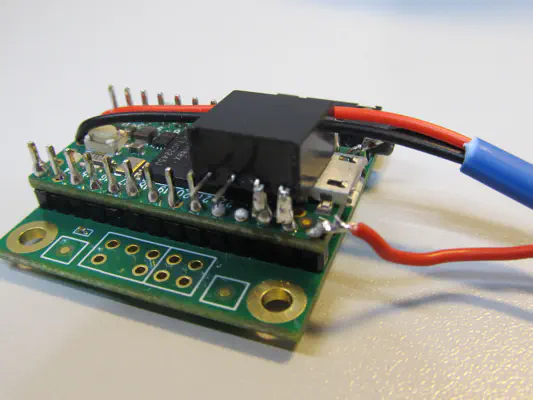
Voltage transformer, soldered to GND and 3.3V of the Teensy
Not in the photo: Place the voltage transformer in front of you with the label facing up and the feet pointing towards you. Now bend the two left feet upwards by 90° as close to the voltage transformer as possible.
See photo: Now place the voltage transformer on the Teensy with the label facing downwards. Make sure that the bent feet are on the left of the two single pins that protrude from the 3.3V contact and GND contact (to the right).
Now you can solder both contact points.
Preparing the plug connection (part 1: header 6-pin)
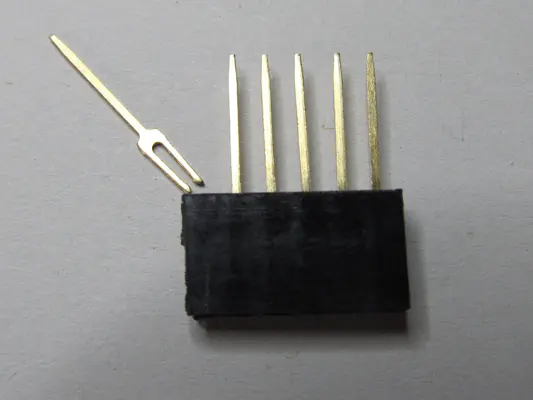
Pin 1 pulled out
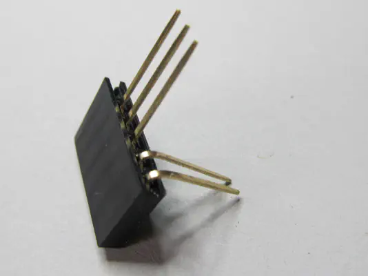
Pin 5 and 6: First bend 90° backwards
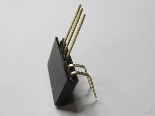
Second bend down
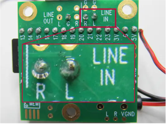
Both pins soldered to the line-in of the audio shield
- Click through the bending tabs (1.-4.) to see detailed photos of the individual steps.
- Pull pin 1 (far left) out of the connector. It is no longer needed.
- First bend pins 5 and 6 (far right) backwards by 90°. Then bend them downwards by approx. 75 degrees with a gap of approx. 4 mm. Both pins must reach the line-in contacts of the audio shield and be soldered there.
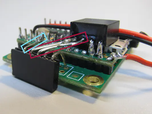
Soldered header 6-pin
- The header 6-pin must fit on the end of the radar module. It can help if you attach the radar module to the audio shield to bend the pins. The necessary steps are explained from here in the "Assembly" chapter.
- Bend enable (pin 2) to pin 17 of the Teensy and solder together (just fits).
- Connect Gnd (pin 4) and Vcc (pin 3) diagonally to the output of the voltage converter (see photo). You may have to bridge this with solder or a short wire. The photo at the bottom of the page shows another top view that may be helpful.
Preparing the plug connection (part 2: header 4-pin)
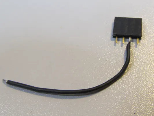
Prepared header 4-pin.
-
You must solder one end of the cable (4cm) to one of the inner contacts of the header 4-pin.
Final result
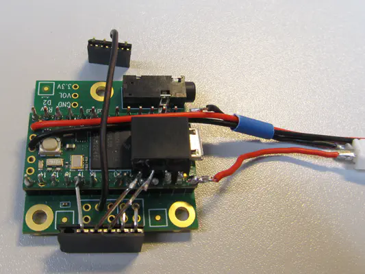
Final result after executing all steps
-
Solder the other end of the cable coming from the header 4-pin to GND (lineout or mic) of the audio shield.
-
In the end, everything should look like the photo.